Electronic Systems Design for EMC Compliance
Description
Well-designed electronic systems operate reliably in their intended electromagnetic environment. These systems are not affected by voltage spikes on their power or signal lines; they function normally in the presence of strong electric or magnetic fields; and the systems’ own fields do not interfere with other systems nearby. In a well-designed system, the cost of grounding, shielding and filtering is usually a negligible percentage of the overall system component costs.
Unfortunately, many electronic systems are not well designed. It is not unusual for a company to spend millions of dollars and thousands of man-hours attempting to track down and correct system malfunctions that are the direct result of improper grounding and shielding. This course reviews the fundamental grounding, filtering and shielding concepts that all engineers can utilize to ensure the safety and reliability of their products at the lowest possible cost.
First-pass compliance with electromagnetic compatibility requirements is not achieve by following a set of design rules. Instead, it is largely a matter of recognizing where the signal and noise currents will flow in a given system. With a little practice, following these currents can be a relatively straight-forward process, even in complex systems with many circuit boards. Taking the time to ensure that both signal and noise currents are routed appropriately generally results in products that meet all electromagnetic compatibility and signal integrity requirements on time and on budget.
Of course, recognizing the sources and coupling paths associated with signal and noise currents requires a bit of knowledge related to the high-frequency behavior of circuits and components, field-coupling, transmission lines, and antennas. Quantifying the impact of these currents involves knowing a little about EMC test requirements, vulnerable circuits, and simple modeling techniques routinely used by EMC engineers.
This course stresses the fundamental concepts and tools that all electronics engineers can employ to avoid electromagnetic compatibility and signal integrity problems. Students completing the course will be able to make good decisions regarding board layout and system design for EMC. They will also be introduced to tools and techniques for quickly reviewing designs in order to flag potential problems well before the first hardware is built and tested.
Continuing Education Credit: 1.2 CEUs, 12 PDHs
Course Outline
Part 1 - Important Fundamental Concepts
- Introduction
- Overview of Electromagnetic Compatibility
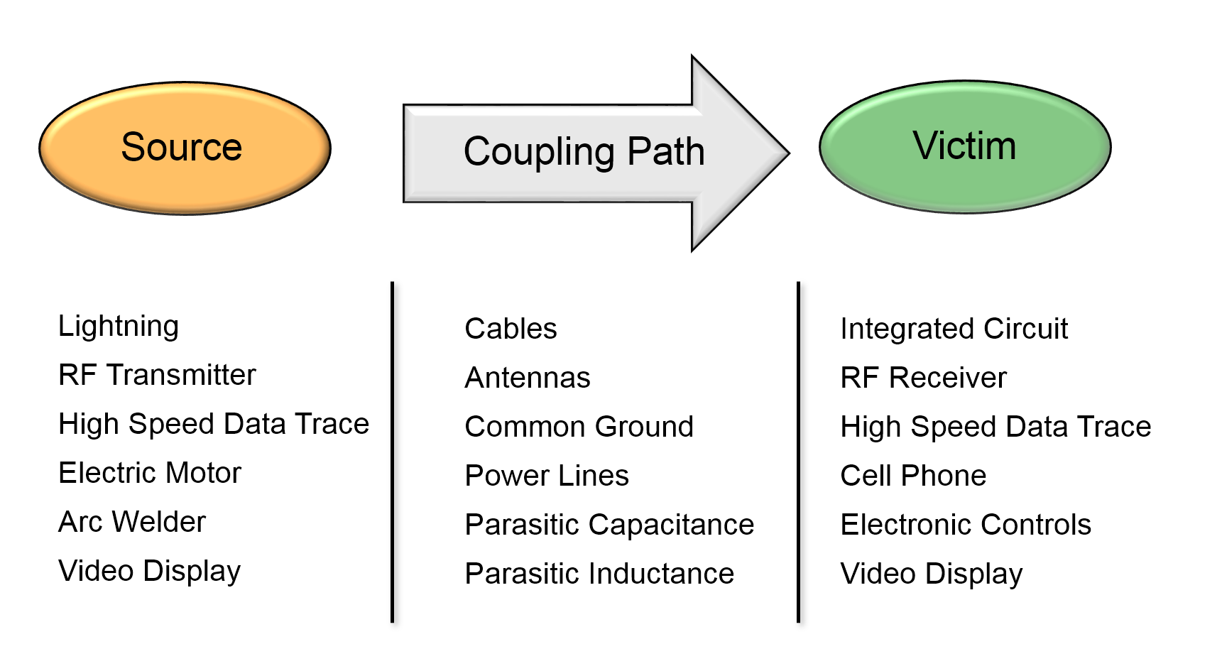
- Coupling Mechanisms
- Signal Routing and Termination
- Tracing Current Paths / Concept of Least Impedance
- Transition Time Control
- RLC Circuits
- Transmission Lines
- Identifying the Unintentional Antennas
- Essential Elements of an Antenna
- What Makes a Good Antenna
- What Makes a Poor Antenna
- Noise Sources and Coupling Mechanisms
- Integrated Circuits as Sources of EMI
- Parasitic Oscillations and Unexpected Noise Sources
- Coupling Between Noise Sources and Antennas
- Differential Mode to Common Mode Conversion
- Grounding
- Ground vs. Current Return
- Ground Structures and Grounding Conductors
- Strategies for Mixed-Signal PCB Layout
- Managing Current Return Paths
- Managing Ground
- Design Examples
- Filtering
- Insertion Loss
- First-Order Low-Pass Filters
- Second-Order and Third-Order Low-Pass Filters
- Common-Mode Chokes
- Component Parasitics
- Shielding
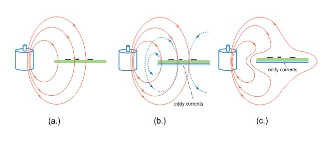
- Electric Field Shielding
- Magnetic Field Shielding
- Shielding to Reduce Radiated Emissions
- Cable Shielding
Part 2 - Advanced Design and Modeling Techniques
- DC Power Distribution and Decoupling
- Effective Power Distribution Strategies
- Choosing and Locating Decoupling Capacitors
- Low-Inductance Capacitor Connections
- Isolating PLLs and Other Sensitive Devices
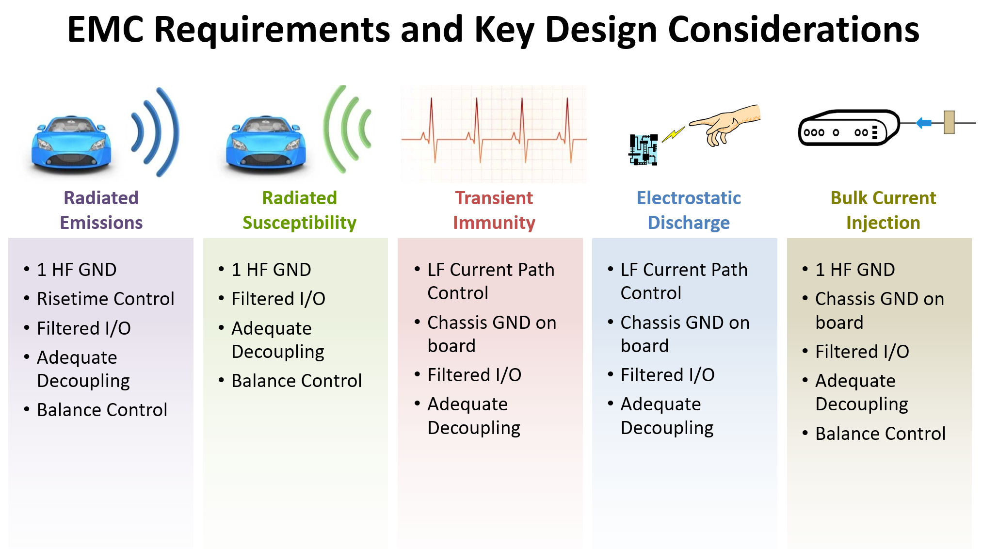
- Key System-Level Design Considerations
- For Radiated Emissions Tests
- For Conducted Emissions Tests
- For Radiated Susceptibility
- For ESD and Transient Tests
- An EMC Compliance Strategy
- Which Circuits or Nets Deserve Attention?
- Which Transition Times Require Control?
- Which Current Paths need to be Traced?
- Which Nets Have a Balance Mismatch (and does it matter)?
- Where are the Antennas?
- Where will ESD and Transient Currents Flow?
- What's the Worst That Could Happen?
- Computer Modeling Tools
- Schematic and Board Layout Tools
- Circuit Solvers
- Field Solvers
- Full-Wave Modeling Tools
- Design Rule Checkers
- Maximum Emissions/Coupling Calculators
- Modeling Examples
- Specific Design Examples
- DC-to-DC Converters
- GPS Receiver
- Power over Ethernet (PoE), Power over Coax (PoC)
- Power Inverter / Motor Driver
- Others Provided by the Class
- Course Summary
- Review of Key Concepts
- Resources for EMC and Signal Integrity Engineers
Course Instructor

Dr. Todd H. Hubing is a Professor Emeritus of Electrical and Computer Engineering at Clemson University and former Director of the Clemson Vehicular Electronics Laboratory. He and his students at Clemson have worked on the development and analysis of a wide variety of electronic products. EMC design rules can vary greatly depending on whether you are designing high-speed computing equipment, low-cost mixed-signal consumer products or high-power industrial controls; but the basic EMC principles are the same in all industries. By applying these principles in an organized manner, it is possible to review a design circuit-by-circuit to guarantee that any particular EMC requirement will be met. This approach is more effective than the blind application of design guidelines and is the primary emphasis of every EMC design class taught by Dr. Hubing.