EMC Question of the Week: November 3, 2025
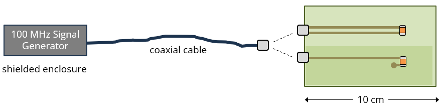
A 100-MHz signal generator in a shielded enclosure drives a matched load on a circuit board through a 50-cm coaxial cable. On the board, the signal travels 8 cm on either a pair of coplanar traces or a microstrip trace. Common-mode current and radiated emissions are reduced by choosing the
- coplanar traces
- microstrip trace
- path with the lowest inductance
- path with the better impedance match
Answer
The best answer is “b.” The common-mode voltage that drives the cable relative to the board is determined by the change in the electrical balance at the interface. It is independent of the transmission line inductance or characteristic impedance. Since the coaxial cable is perfectly unbalanced, the microstrip trace (which is very unbalanced) generates relatively little common-mode voltage. The coplanar traces (which are balanced) generates a common-mode voltage equal to half the signal voltage at the interface.
In this experiment, the common-mode voltage can be determined precisely from the signal voltage and the computed imbalance factors of the circuit board transmission lines (VCM = Δh × VDM). The common-mode current on the cable is this common-mode voltage divided by the input impedance of the dipole antenna formed by the source/cable and the circuit board.
Of course, a mismatch in the characteristic impedances of the transmission lines can affect the differential-mode voltage and therefore also the common-mode voltage. But, in this configuration, the impact of any impedance mismatch is minor compared to the large differences in the imbalance factor between these two options.
Note that if the source had been differential and the cable had been a differential pair, the coplanar traces would have been the best choice.
Have a comment or question regarding this solution? We'd like to hear from you. Email us at